Programmable Christmas LEDS with Arduino
This is one of my first Arduino projects where I’ll be using Fritzing software for designing and producing my PCB. Also I tried building a nice, open case for it.
I wanted to create a sort of Christmas Lights Loop that loops in 6 different schemes. Like a random one, a simple loop, a quick loop and so on.
Therefore I bought a rotary switch and an IC and off I went. See it in action:
First of all, I created my circuit on breadboard. Since I’m not an electrotechnician or programmer at all, I used the circuit and code provided by Arduino and changed it a little bit.
For me the capacitor didn’t work out, so I (or I have to admit, my boyfriend), plugged in a 100 kΩ resistor instead of the capacitor.
So this is the circuit, and breadboard scheme:


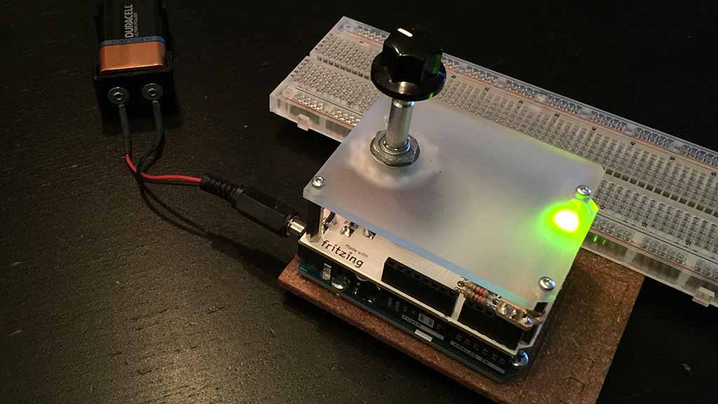
Testing the circuit.
Note that in this image an ethernet-shield is placed upon the Arduino Uno. This is quite unnecessary for this project but it was attached to it when I took this photo…

Then I ordered my PCB at Fritzing and two weeks later this beautiful circuit board arrived:

Here you can see some components I soldered on it…

Now I realized I designed everything far too small 🙁 so we had to made this ‘bridge’ for the LEDs in order to construct the perspex cover properly…

The perspex cover, cut out from a perspex plate using a Dremel.

And the final result:

Of course this one also works without the breadboard glued next to it…
Last but not not least the Arduino code. I have to say that I haven’t code this very properly, I think I can do a better job by using classes or functions, but, hey, it works 😉
 /*
 Shift Register Example
 for 74HC595 shift register

 This sketch turns reads serial input and uses it to set the pins
 of a 74HC595 shift register.

 Hardware:
 * 74HC595 shift register attached to pins 2, 3, and 4 of the Arduino,
 as detailed below.
 * LEDs attached to each of the outputs of the shift register

 Created 22 May 2009
 Created 23 Mar 2010
 by Tom Igoe
 and some code by susan odendaal

 */

//Pin connected to latch pin (ST_CP) of 74HC595
const int latchPin = 8;
//Pin connected to clock pin (SH_CP) of 74HC595
const int clockPin = 12;
////Pin connected to Data in (DS) of 74HC595
const int dataPin = 11;

int lednr = 0;
// rotary switch no:
const int buttonPinRed = 7;
const int buttonPinOrange = 6;
const int buttonPinYellow = 5;
const int buttonPinGreen = 4;
const int buttonPinBlue = 3;
const int buttonPinViolet = 2;

// variable for reading the pushbutton status:
int buttonStateRed = 0;
int buttonStateOrange = 0;
int buttonStateYellow = 0;
int buttonStateGreen = 0;
int buttonStateBlue = 0;
int buttonStateViolet = 0;


void setup() {
//set pins to output because they are addressed in the main loop
//pinMode(latchPin, OUTPUT);
 pinMode(dataPin, OUTPUT);
 pinMode(clockPin, OUTPUT);
 pinMode(buttonPinRed, INPUT);
 pinMode(buttonPinOrange, INPUT);
 pinMode(buttonPinYellow, INPUT);
 pinMode(buttonPinGreen, INPUT);
 pinMode(buttonPinBlue, INPUT);
 pinMode(buttonPinViolet, INPUT);

 Serial.begin(9600);
 Serial.println("reset");
}

void loop() {
 buttonStateRed = digitalRead(buttonPinRed);
 buttonStateOrange = digitalRead(buttonPinOrange);
 buttonStateYellow = digitalRead(buttonPinYellow);
 buttonStateGreen = digitalRead(buttonPinGreen);
 buttonStateBlue = digitalRead(buttonPinBlue);
 buttonStateViolet = digitalRead(buttonPinViolet);

digitalWrite(0, LOW);
// int bitToSet = Serial.read() - 48;

//blinking scheme red
if (buttonStateRed == HIGH)
{
for (int x=0;x<8;x++)
 {
 registerWrite(x, HIGH);
 delay(250);
 }
for (int x=6;x>0;x--)
 {
 registerWrite(x, HIGH);
 delay(100);
 }
}
//einde blinking scheme red

//blinking scheme Oranje
if (buttonStateOrange == HIGH)
{
 int x = random(8);
 registerWrite(x, HIGH);
 delay(100);
}
//einde blinking scheme oranje

//blinking scheme Yellow
if (buttonStateYellow == HIGH)
{
 int x = random(8);
 registerWrite(x, HIGH);
 delay(500);
}
//einde blinking scheme Yellow

//blinking scheme green
if (buttonStateGreen == HIGH)
{
for (int x=0;x<8;x++)
 {
 registerWrite(x, HIGH);
 delay(100);
 }
}
//einde blinking scheme green

//blinking scheme blue
if (buttonStateBlue == HIGH)
{
for (int x=0;x<8;x++)
 {
 registerWrite(x, HIGH);
 delay(x*40);
 }
}
//einde blinking scheme blue

//blinking scheme Violet
if (buttonStateViolet == HIGH)
{
for (int x=0;x<8;x++)
 {
 registerWrite(x, HIGH);
 delay(100);
 x++;
 }
}
//einde blinking scheme violet
}

// This method sends bits to the shift register:

void registerWrite(int whichPin, int whichState) {
// the bits you want to send
byte bitsToSend = 0;
// turn off the output so the pins don't light up
// while you're shifting bits:
digitalWrite(latchPin, LOW);

// turn on the next highest bit in bitsToSend:
bitWrite(bitsToSend, whichPin, whichState);
// Serial.print("het led is ");
// Serial.println(whichPin);

// shift the bits out:
shiftOut(dataPin, clockPin, MSBFIRST, bitsToSend);

// turn on the output so the LEDs can light up:
digitalWrite(latchPin, HIGH);

}
Many thanks to Tom Igoe. I’ve used his code (and added some) on Arduino CC to build this gadget.
Williampr
mei 26, 2016 at 05:46This is one awesome forum post. Keep writing. Gamarra
Doom Wallhack
mei 26, 2016 at 14:03Hey there this is kind of of off topic but I was wondering if blogs use WYSIWYG editors or if you have to manually code with HTML.
I’m starting a blog soon but have no coding experience so I wanted to get advice from someone with experience.
Any help would be greatly appreciated!
susan
juni 19, 2016 at 12:11That depends on the CMS you’re using (e.g. WordPress) and the plugins you’re using.